PATENTS & IP
Power Enhancing Devices
Piezoelectric Energy Harvester
Inventors: Raj Chowdhury, MS, Sumit Patankar, MS
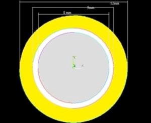
Fig. 1: Plan view of the disc bender element.
The innermost concentric circular area in Fig. 1 shows the piezo element. The piezo element is coated on top with silver which acts as one of the electrodes. The outermost concentric circular area in the figure (on which the piezo element is mounted) is made of brass and acts as the other electrode. Other common electrodes replacing silver and brass can also work. The middle circular area shown in this top view is the insulation circumferencing the edge of the piezo material. Most common insulation materials can work to serve this purpose.
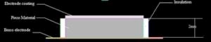
Fig. 2: Side view of the disc bender element and dimensions.
Fig. 2 shows the side view of the disc bender element and shows the other dimensions and materials not shown in Fig. 1. These disc bender elements are placed between two layers of patterned conducting foils. The conducting foil is patterned similar to the arrangement of the keys in a notebook or a cell phone keypad (or other portable devices for which the set-up is being used), that is, the foil will have conducting material deposited wherever the keys are placed in the device.
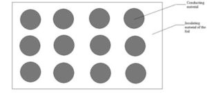
Fig. 3: Top view of patterned conducting foil layout.
Fig. 3 shows the top view of an approximate foil. The pattern shown in the diagram is only an example and the actual pattern will depend on how the keys in the portable device are placed.
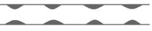
Fig. 4: Side view of foils and disc bender mounts.
Fig. 4 shows the side view of two conducting foils between which the disc bender mounts. The top foil will touch the silver electrode and the bottom foil will touch the brass electrode at all times. Instead of the conducting foils, electrical wires can also be used as shown in Fig. 6. This is recommended to be tried first. These wires need to be soldered to the two electrodes.
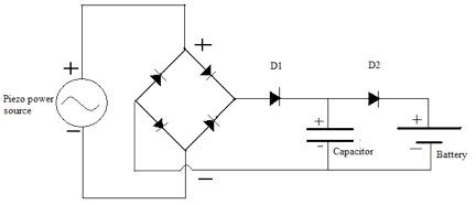
Fig. 5: Charging circuit diagram.
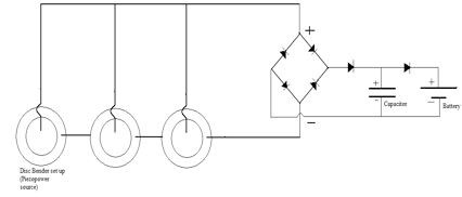
Fig. 6: Alternate configuration with soldered wiring.
Fig. 5 shows the circuit diagram of the charging circuit. The AC-type power generated by the piezo element upon exertion of pressure by the user is converted into DC power by the rectifier circuit shown in Fig. 5. This power charges the capacitor shown in the figure. The capacitor used here has a capacitance of 1000 µF for charging a Li-ion battery set (of two) of a notebook. The capacitor specification will vary depending on the portable device that is being charged. Pre-charge the capacitor before typing.
When the instantaneous voltage of the capacitor exceeds the instantaneous voltage of the battery, the capacitor discharges into the battery, charging it. Diodes D1 and D2 are used to limit the reverse flow of current from the capacitor to the rest of the circuit and from the battery back to the capacitor respectively.